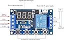
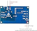
This is the JZ801 programmable relay module. This vtext has five sections: 1. An overview of what the product does 2. How to wire the module 3. A painfully detailed explanation of how to program the device 4. A description of all seven operating modes and 5. Some operating notes Section 1: The Overview This module is very straightforward. It will turn on an electrical circuit for a given amount of time, and it will turn off an electrical circuit for a given amount of time. These times can be as short as a tenth of a second, or as long as 16 hours and 39 minutes. The device will allow you to cycle between the timed on and off states up to 999 times, or infinitely if you prefer. There's also a user-supplied push-button trigger involved whose function varies based on the selected operating mode, or you can substitute a 3-24V trigger signal to do the job of the push button. The electrical switching is provided by a relay and these three terminals. In the OFF state, the center common terminal is connected to this normally closed terminal, and in the ON state, the center common terminal is connected to this normally open terminal. You can power the device using either a Type-C or micro-USB connector, or you can power it using anywhere from 6 to 30 volts of direct current. The device has a diode that prevents damage should you confuse the positive and negative leads of your power supply. The digital display normally stays on constantly, but has a "sleep mode" option that will turn off the display after 5 minutes while the device continues to operate. Section 2: Wiring Let's take a look at how to wire this module. You can supply power to the device by using a USB cable plugged in here, or you can use anywhere from 6 to 30 volts of direct current, positive connected to this terminal, negative to this terminal. In most operating modes, you'll need a way to trigger this device. That's simply a way of saying, "Start now." This trigger can be as simple as a push button or as complex as a high level trigger signal source. Let's keep it simple with a momentary contact push button trigger. A neat and tidy way to do this is to insert a small jumper cable between the system ground here and the trigger ground here. Then connect your push-button trigger between the positive power terminal here and the trigger terminal here. If you're not happy with this jumper cable, you can remove it and simply short these two contacts directly on the printed circuit board. If you want to use a high-level trigger signal source, a momentary 3 to 24 volt trigger can be applied between these two terminals. The wiring on the relay terminals will be quite dependent on your specific project, but I'll show you how I wired my test stand to experiment with this module. I have a 6V power supply here, and I have a red indicator light connected to the off or normally closed terminal, and a green indicator light connected to the on or normally open terminal. I'm keeping it simple with the jumper cable and momentary contact push button trigger shown here. We'll be using this test stand when we get to the section explaining the 7 operating modes. Section 3: Programming Assuming you have your module powered and ready to go, here are the steps required to get this device programmed. First, we need to define some terms. Press and hold for 3 seconds. Means just that. Press the button for 3 seconds, then release. Pressing and holding for less than 3 seconds will end in an unwanted result. Short press means to short press the button just long enough to make electrical contact. Long press means to press and hold the button while watching the display. Doing this at the right time will prevent you from having to press the up or down button hundreds of times when you're working with large numbers. There are four primary settings that need to be programmed. First, you need to select the operating mode. I'll explain the differences between modes in the next section. Second, you'll need to program the relay on time. Logically, this is called OP. Third, you need to program the relay off time. Of course, this is called CL. Finally, you need to program the number of on/off cycles you'd like. Naturally, this is called LOP. In order to make sense of all this, we need to begin with a common reference point. Let's get started. Power up your module. The display should flash the letter P followed by a one or two digit number. This is flashed three times, then replaced by three zeros. These three zeros indicate the module is ready to start its on/off cycle with your trigger. Short press the stop button. One of two things will happen. Either the display will flash off for a few seconds, which is bad, or it might flash on for a few seconds. This is good. If the display flashed on, leave it alone. If it flashed off, short press the stop button one more time to see the coveted on display. When you're ready to use this module in your project, this is one way to keep the module powered, but deactivate the relay. Next, we'll need to select one of seven operating modes. Again, I'll explain the differences later, but for now, we're going to use mode 3.1. Press and hold the Set button for three seconds. The display will show the letter P followed by a one or two digit number. This is your operating mode. Short press the Up or Down button to cycle through the seven modes until you get to mode 3.1. Short press the Set button. The letters OP flash three times, followed by a three-digit number. This is the length of time the relay will be on. Short pressing the Up or Down button at this point will increment the display one digit up or down. Long pressing the up or down button will have the digits increment at high speed. Very convenient when working with large numbers. For now, we want the display to read 004. If the display reads 004 decimal, it means the relay will be in the on state for 4 seconds. Short press the stop button. If the display reads 00.4, it means the relay will be in the on state for 4 tenths of a second. Short press the stop button again. If the display reads 0.00.4, it means the relay will be in the on state for 4 minutes. Let's keep it simple and keep the display at 00.4 for a 4 second on time. Now, short press the Set button. The letters CL flash three times, followed by a three digit number. This is the time the relay will be in the off state. Using the same short and long presses on the up and down buttons, set the display to 006. Then, short press the Stop button as many times as necessary to make sure we're working with a six second duration, with the decimal appearing only at the end of the display. Now, short press the Set button one more time. The letters LOP will flash three times followed by a three digit number or three dashes. This is where you set the number of times you want the relay to cycle through the on/off functions before stopping. Setting the display to three dashes will cause the relay to cycle forever. Setting the display to 003 will cause the relay to cycle three times, then stop. The relay will always stop in the off state. Now press and hold the set button for three seconds. If we did this right, the display should flash P3.1 three times, then display three zeros. This means the module is ready to be triggered to start by using your trigger button or trigger signal from an external device. You can see at a glance what your timer settings are by giving the Set button a short press now. The display will cycle through the on time, the off time, and the number of cycles before returning to the 000 ready to trigger state. Some things to consider: Some operating modes do not use a relay off time. When programming these modes, the module will not permit you to enter an off time. Any off time left in the system will be ignored. Of course, without an off time, there's no need for a cycle time, so that setting won't be available during programming either. Some operating modes have an on and off time, but no cycle time. Operating mode 3.2 does not need a start trigger. When using Mode 3.2, make sure that whatever is connected to your module is safely powered down to prevent an unintentional start. Section 4. Operating Modes There are seven operating modes. Here's how they work. Mode P1.1 has an ON time only. When triggered to start, the relay will immediately turn ON for the set time, then turn OFF ready to be triggered again. The module will ignore any trigger button pushed during the ON time. Mode P1.2 has an ON time only. When triggered to start, the relay will immediately turn ON for the set time, then turn OFF ready to be triggered again. If the trigger button is pressed during the on state, the relay will remain on and the on timer will be restarted. Mode P1.3 has an on time only. When triggered to start, the relay will immediately turn on for the set time, then turn off ready to be triggered again. If the trigger button is pressed during the on state, the relay will immediately switch to the off state, reset the timer, and is ready to be triggered once again. Mode P2 has an on time and an off time, but no cycle option. When triggered, the relay will remain in the OFF state for the programmed OFF time, then switch to the ON state for the programmed ON time, then return to the OFF state, ready to be re-triggered. The module will ignore any trigger button push during the OFF state. If the trigger button is pushed during the ON state, the OP timer will continue to run, but the relay will immediately switch to the OFF state. When the OP timer is completed, the module is ready to be triggered again. Mode 3.1 has an On Time, an Off Time, and a Number of Cycles setting. When triggered, the module immediately switches to the On state for the On Time, switches to the Off state for the Off Time, and continues this action for the programmed number of cycles. If the trigger button is pressed at any time during these cycles, the relay will immediately switch to the off state, ready to be restarted with the full number of cycles. Mode 3.2 has an on time, an off time, and a number of cycles setting. When powered, the module displays the mode number for 3 seconds, then switches to the on state for the on time, switches to the off state for the off time, and continues this action for the program number of cycles. The start trigger is completely ignored and has no effect in this mode. Be aware that this mode will energize any connected devices without a trigger button push. Mode 4 has an on time only. When triggered, the relay immediately switches to the on state for the on time, then switches back to the off state ready for another start trigger. If the trigger button is pressed at any time during the on state, the relay will remain in the on state and restart the on timer. Section 5: Operating Notes When the module is not being programmed, you can set the option for the Display Sleep Mode. The Sleep Mode will turn off the display after 5 minutes but keep the module in operation. To use this feature, press and hold the Stop button for 3 seconds. When you release the button, the display will read "OD" or "CP". Clearly, OD indicates the display is always on and CP indicates the display will go to sleep after 5 minutes. Press and hold the stop button for 3 seconds and release until your desired option is displayed. As a safety feature, short pressing the stop button during the operation of the module will immediately bring the relay to the off state and keep it there regardless of the operating mode. However, the on and off times will continue to run as will the cycle count. Short pressing the stop button again will resume the active on/off state and cycle count. If you short press the Set button during the operation of the module, you'll get a quick display of the on, off and cycle count if applicable, but the timer that is currently in use will pause. It will resume counting only when the display returns to that timer. A warning again about operating mode 3.2. This mode does not use a trigger and will power any connected equipment three seconds after the module is powered on. If you need to set a programmable time greater than 500 seconds, long press the down button for a quick ride and reverse from 999. My wild guesses on what the module letter codes actually mean. The relay on time is labeled "OP". I think "OP" could mean that the relay common terminal is now connected to the normally open terminal and therefore is in the on state. The relay off time is labeled "CL". i think cl could mean that the relay common terminal is now connected to the normally closed terminal and is therefore in the off state the number of cycle setting is labelled lop i think lop could stand for length of program or loop The Display Sleep option is labeled CP. I think CP could stand for Conserve Power. The Display Always On option is labeled OD. I think OD might stand for Ordinary Display Mode. Being on the spectrum requires that I try to make sense of this stuff. I hope this video helps you make a decision on whether or not this is the right module for your project and eases the learning curve on the programming front.
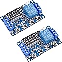
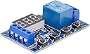
![[2 Pack] DC 6-30V Timer Relay Programmable Delay Relay Module Cycle Timer with LED Display / 5V Micro USB, Smart Home Controller](https://m.media-amazon.com/images/I/81WS9ok2FqL._AC_SL3840_.jpg)