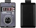
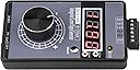
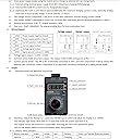
This review is specifically for the product that Amazon’s listing calls “Adjustable 4-20mA Signal Generator Current Voltage Analog Simulator 0-10V/0-22mA Signal Sources for Value Adjusting PLC Controller Panel LED Testing Calibration”. The manufacturer’s brand name is allegedly “TKXEC”, and their user’s manual calls it model QH-VISG2-ED (note the ‘D’ suffix); the same basic product is also sometimes sold as model QH-VISG2-EN (‘N’ suffix), and that version does NOT come with the Lithium-Ion battery. The product being reviewed here, QH-VISG2-ED, DOES include the battery. The product itself does not have the brand name or model number anywhere on it. Henceforth in this review, this product will be referred to as the “Tester”.The Tester comes with a single page User’s Manual, a short USB-A to Micro USB cable, a small screwdriver that fits the screws on the unpluggable 6-position terminal block, a set of four alligator clips, four rubber “boots” for insulating the clips, and a set of six tiny pin lugs which may be optionally soldered over the stripped ends of stranded test lead wires (as large as 22AWG) and then soldered at the tips of the pins. The clips, boots and pin plugs are for making your own test leads. I recommend using wire with a high strand count, silicone rubber insulation, and 22AWG size.This Tester is clearly intended to be used for testing certain kinds of industrial equipment that responds to low voltage DC control signals or DC milliamp (mA) ‘current loop’ control signals; a MODE pushbutton easily switches between the two types of signal. Due to the tedious method of adjusting the output signal over its assigned range, this Tester is NOT ideal for quick and easy adjustments of these signals. The large adjustment knob has 20 detent positions per rotation (the knob operates an internal rotary encoder, rather than a potentiometer) and it can take many turns of the knob to swing the output signal from one end of the assigned signal span to the other end; this characteristic can be good or bad, depending on how the Tester will be used.The Tester has a fairly elaborate internal circuit, including what seems to be a few tiny switching regulators that produce higher working voltages and polarities than the simple power source(s) provide.The Tester is primarily powered from its internal Lithium-Ion battery, which is rated for 3.7V and 1000mAh. The Tester comes with a short (about 14”) USB-A to Micro USB cable, and this can be connected to any USB-A port, whether it be a USB port on a computer, or something like a mobile phone charger/power supply/”wall wart”, but such a supply needs to be rated for at least 1A (which means most such devices will be adequate). A multi-color LED on the Tester flashes to indicate a charging battery, and it glows steadily during use to show charge above 80% (Green), 40~80% (Amber), and below 40% (Red). Pressing the MODE button for 1 second will cause the display to show the battery voltage for a few seconds; the accuracy of this has not been established.It takes about 4 hours to fully charge, and the manufacturer claims that the battery will power the Tester for about 5 hours. For longer periods of use, the Tester can be continuously powered from the USB power source as described above. If that is not an available option, the Tester may also be continuously powered from an external regulated 24VDC power supply, connecting via two positions of the 6-position unpluggable terminal block on top end of the Tester. Note that this Tester cannot derive its operating power from a 4-20mA current loop, which is just one of the several configurations it can be in; in this sense, this Tester cannot be used as a true “2-wire transmitter” surrogate.The Tester has one ‘mode’ of operation for outputting a specified DC voltage ‘signal’, and in this mode it can be configured to output any of the following signal spans: -10 ~ +10V, -5 ~ +5V, 0 ~ 10V, 2 ~ 10V, 0 ~ 5V, 1 ~ 5V, 0 ~ 3.3V, 0 ~ 2.5V, 0 ~ 1V, -10 ~ 0V. The Tester has three ’modes’ of operation for modulating the mA current in a ‘current-loop’; it can be connected as a mA signal source, where the ‘loop’ is simply this Tester and the ‘loop receiver’ (which can be a PLC/DCS/SCADA mA input, or the mA control input of a positioning valve or variable frequency motor drive (VFD), or the mA input of a chart recorder, data-logger, etc). It can also be connected as if it were a “2-wire” 4-20mA transmitter, although since the Tester cannot itself be ‘loop powered’, it is not a true “2-wire” device. It can be configured as a “3-wire” transmitter or as a “4-wire” transmitter; the power source must be 15~24VDC, and it will be electrically commoned with one side of the output current loop (so really not a true “4-wire” transmitter surrogate). Note that the included User’s Manual does not show all of the possible variations on how the Tester can be connected in its Current mode of operation. The available current signal spans are: 0~20mA, 4~20mA, 0~22mA.The Tester has an unpluggable 6-position ‘compression box’ terminal block for connecting output signal wires and the optional external power source. It is not obvious which terminal positions must be used for each wiring configuration; the User’s Manual has wiring diagrams...don’t lose it! The Tester has four ‘controls’; the Battery Power switch (affects only the internal battery, NOT the USB power option or the external 24VDC power source option), MODE pushbutton, the knob (as turned) and the knob (as pressed like a button). It has four ‘indicators’: the Battery status LED, the Voltage Mode LED, the Current Mode LED, and the 4-digit 7-segment LED display. It is probably this LED display’s power requirements that prevent the Tester from being operated in a “loop powered” scheme. Note that the displayed output signal value (voltage or current) is NOT a measurement of the output signal; the Tester is NOT a meter!In basic operation, the user presses the MODE button to select Voltage or Current mode, then turns the knob to scroll through the selected voltage or current span. ALL other configurations and selections must be made by changing parameters in the Tester’s MENU system, as described below.The Tester includes a simple default memory; when the user has selected a desired voltage or current value using the knob, the knob may be pressed down briefly to save that value as a default for the next time the Tester is turned on. One voltage value and one current value may be saved in this way. The Tester displays a “. . .” pattern to show that saving is taking place.In addition to the voltage and current spans mentioned previously, the Tester allows configuring the display to show the set values in engineering units. For Voltage Mode, the units can be Real Voltage (V), 0~100% of selected span, 0~50Hz (there is no 0~60Hz option), and 0~1500; the “Hz” option does not mean that the Tester output is a frequency, rather it simply allows the setting to be made in units that correspond to the output frequency of a variable frequency drive (VFD) that has 50Hz as its maximum output, corresponding to the driven motor’s highest speed. It seems inconceivable that the manufacturer if the Tester did not include an option for 0~60Hz. I don’t know what the 0~1500 units are for. For Current Mode, the units can be Real Current (mA), 0~100% of selected span, 0~50Hz, (there is no 0~60Hz option).The Tester can be configured to have more or less sensitivity of the knob for adjusting voltage and current settings. The knob’s rotary encoder has 20 detents (clicks) per full rotation, and by default the displayed voltage or current setting will increment or decrement by 1 for each detent of rotation. The user can configure the displayed setting to be changed at the 00.0x position (“Fine” mode) or at the 00.x0 position (“Coarse” mode), and also the amount of change per detent can be set from 1 to 50; in “Coarse” mode with a change value of 50, just a couple knob turns are required to adjust through the entire selected span, while at the other extreme, in “Fine” mode with a change value of 1, many knob turns are required to adjust through the same span. The digit position being changed will “roll over” to affect the digits to its left. Unfortunately, it is quite unintuitive and somewhat tedious to change the programmed parameters necessary to configure the knob sensitivity.An alternative to the Coarse/Fine adjustment mode of the Tester’s so-called “Point Mode”, and this is even more elaborately configured using parameters. For example, if the Tester will be used such that only two output voltages are required, perhaps 2V and 7.5V, the Tester’s Voltage Mode can be configured to be in Point Mode, have 2 points selected, and have those two points configured to be 2V and 7.5V. Configured in this way, turning the knob any amount clockwise will immediately result in an output of 7.5V, and turning the knob any amount counter-clockwise will result in an output of 2V. Up to 9 ‘points’ may be configured (naturally 2 points is the minimum), and Voltage and Current Modes can each have their own quantity and set of output values. Regardless of how other parameters may configure the span for each mode, voltage and current, when in Point Mode the Tester always uses a Voltage Mode span of -10 ~ +10V, and Current Mode span is always 0~22mA, in other words the maximum span is automatically selected for use in Point Mode.The Tester’s configurations are determined by the settings of a group (or table) of parameters, with Voltage Mode having its own parameter table, and Current Mode having its own. Confusingly, the parameter numbers for each mode are identical. VERY IMPORTANT: It is imperative that the Tester be selected to Voltage Mode or Current Mode before entering the Menu system and working with the associated parameter table. Things can get really messed up if the user sets Voltage parameters while the Tester is in Current Mode, and vice versa. Do not change the Mode after you are already in the Menu system.The parameters are numbered F001 through F008, and F100 through F109; the former set is for basic configurations such as adjustment sensitivity, span, units and amount of change per knob detent, and the latter set is for Point Mode, with F100 specifying the number of Points, and F101 through F109 specifying the values of each point. Again, each of the two modes, voltage and current, has its own associated parameter table, with its own configurations.To gain access to the Menu system for the purpose of configuring parameters, the user must first ‘enter’ an appropriate ‘password’; the basic parameter set uses the password “+ - - +”, while the Point Mode parameter set, including F100, uses the password “+ - + -“. See the included photos which show what these two passwords actually look like on the display. The knob must be pressed for 3 seconds to get the password prompt, which is initially displayed as “F001”, and the knob must then be turned slightly to display the prompt “_ _ _ _”. Working from left to right, the user turns the knob one detent clockwise to enter a “+”, or one detent counter-clockwise to enter a “-“, and as soon as either “+” or “-“ is entered, the next position to the right becomes active, and quickly all four positions can be entered by this method. Then the knob is pressed briefly, and a parameter number is displayed; the knob can be turned to scroll up and down through the list/table of parameter numbers. For each displayed parameter number, briefly pressing the knob will display the current setting value for that parameter, and the knob can be turned to change it, and when done the knob is pressed again to save that parameter and return to the parameter number list. Turning the knob clockwise until the display reads “FEnd”, and then briefly pressing the knob again, will save all the parameter changes, exit the Menu system, and return to normal Tester operation. Alternately, if the user is in the Menu system and does nothing for 10 seconds, the Menu is exited and the Tester resumes normal operation. Note that both parameter tables are shown in the included user’s manual, and these tables are necessary in order to program the parameters; don’t lose the manual!For Point Mode, it can be tricky and confusing to get into the configuration correctly. The “+ - + -“ Menu must be accessed first, to change the value of F100 to a number between 2 and 9 (the number of desired Points), then the “+ - - +” Menu must be accessed, and F001 changed to a value of 2 to select the Point Mode, then the “+ - + -“ Menu must be accessed again to set the F101 through F109 parameters for the individual Points. This is a real pain to do, but I suppose that most users will never make use of Point Mode. Note that on the LED display, the “+” symbol actually looks like just the left half of a “+”.In each parameter list, three parameters are reserved for modifying the factory-set calibration values. The three values affect the lowest end of the span, the center of the span, and the highest end of the span. It is advised that these values be changed only with great caution, and after first writing down the factory values. Note that the Tester’s specified accuracy is 0.05V or 0.05mA (the Amazon listing says 0.01V or 0.01mA, but I think the former specification is more correct. If you observe errors between the Tester’s displayed values and externally measured values, and the errors are less than 0.05, then there is no advantage to tweaking the calibration values.One final point: The 4-digit LED display can be rather hard to see in certain light conditions, since ambient light and/or glare can wash out the light from the LEDs. My solution was to use a small rectangle of red lighting gel, R26 color, and attach it with super-glue to the front of the LED display (inside the Tester’s case); this dramatically improves contrast and legibility of the display. If you want to do this to your own Tester, buy some “red lighting filter gel R26” (Amazon has many such product listings) and many purchasing options will come up. The ‘gel’ comes in sheets of various sizes, and are intended to be placed in front of theatrical spot lights in order to color the projected light. The plastic material is paper-thin, and the R26 color is the closest match to the color of red LEDs. To access the front of the LED display, use a small Phillips screwdriver to remove the four screws from the rear of the Tester, then lift the back half of the case away from the front half. Pull the knob off of the rotary encoder’s shaft, and use a small wrench to remove the hex nut from the encoder’s threaded bushing. Now, the Tester’s printed circuit board can be removed from the front half of the case, and the LED display is accessible for attaching the red gel.